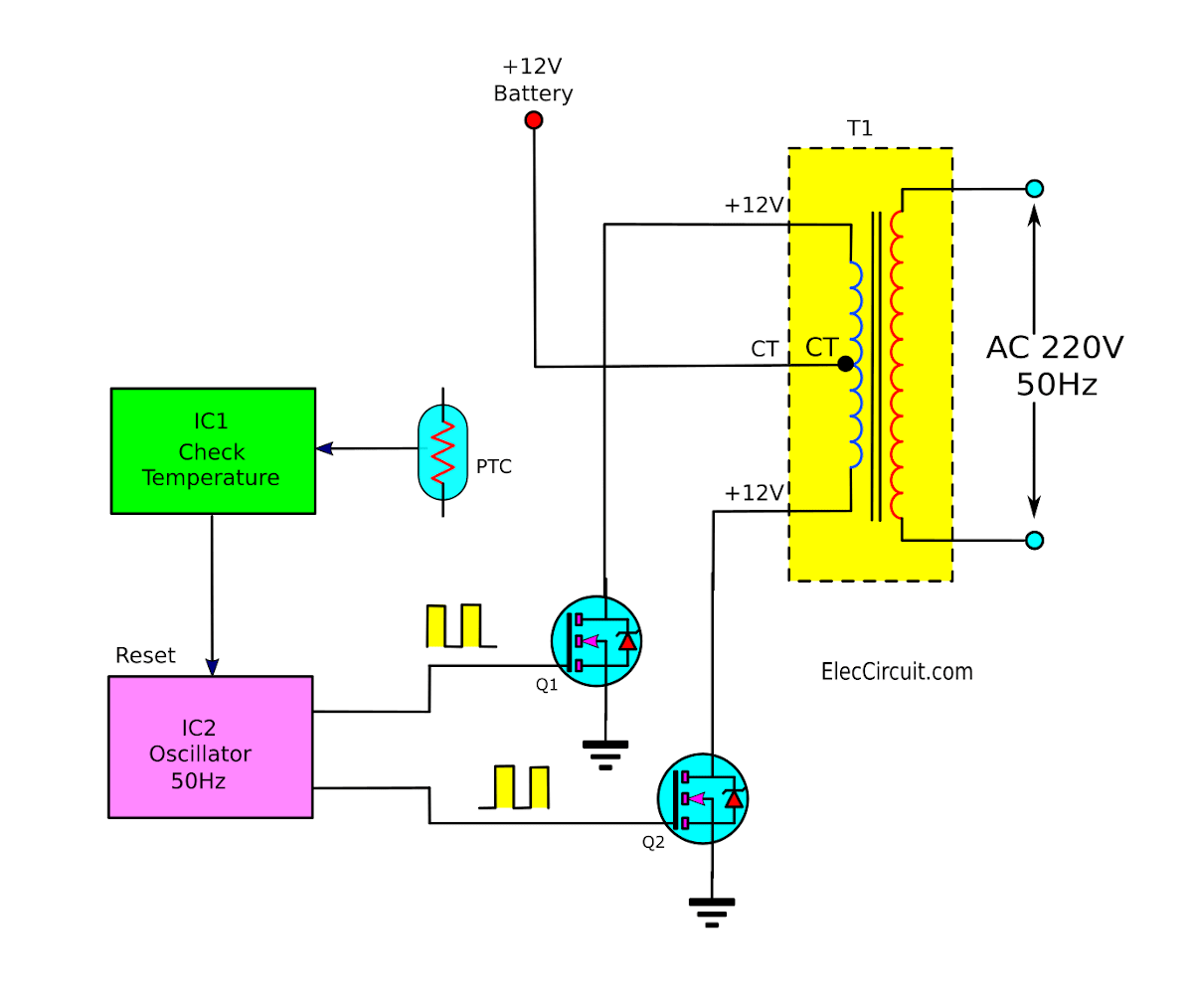
Igbt Inverters Circuit Diagram
Single phase igbt inverter. Phase three gate inverter ti inverters isolated drivers industrial vfd robustness interlocking improving schematic 3phase figure technical Igbt parallel module testing schematic circuit inspection measurement circuitlab created using
Single phase IGBT inverter. | Download Scientific Diagram
Operation of 200 watt inverter diagram Power electronics Igbt circuit equivalent structure working transistor bipolar insulated gate
Simplest pwm modified sine wave inverter circuit using ic tl494
Homemade inverterIgbt working circuit diagram gate power transistor bipolar insulated semiconductor devices figure symbols operations articles basics structures allaboutcircuits Schema invertor 12v 220v 1000wThe basics of power semiconductor devices: structures, symbols, and.
How advanced igbt gate drivers simplify high-voltageInverter circuit volt 12v 220v 500w power diagram 300w simple 220vac 24vdc 2000w 24v pcb eleccircuit schematic transformer circuits watt Interlocking gate drivers for improving the robustness of three-phaseInverter igbt circuit homemade diagrams switch bridge schematics inverters early used.

Inverter igbt
Inverter circuit 500w, 12v to 220vIgbt single phase inverter 5kw-40kw Inverter igbt solar phase 40kw 5kw single grid off tf panel features seriesDiagram block inverter watt inverters 200watt operation circuits control electronic eleccircuit output projects transistors two figure.
Insulated gate bipolar transistor characteristics12v 220v circuit schema 1000w invertor inverter diagram wiring pdf project hub resources What is insulated gate bipolar transistor (igbt)? structure, workingIgbt characteristics circuit explained obtaining resistor.

Circuit igbt diagram characteristics transistor gate bipolar insulated
Introduction to pwm inverters.Inverter circuit pwm tl494 sine wave ic modified using circuits smps pinout application simplest ac ne555 homemade which discuss versatile 6 best – simple inverter circuit diagrams – diy electronics projects1, three phase inverter circuit.
Igbt transistor gate bipolar insulated power mosfet electronics bjt structure channel circuit turn igbts basic than fet high resistance currentVi characteristics of igbt explained Power circuit diagram of an igbt based single phase full-bridgeIgbt drive circuit with discrete component.

Igbt circuit gate voltage high mosfet diode drivers simplify advanced circuits equivalent typical note body there
Pwm inverter diagram block inverters circuit introduction electronic circuits diagrams elementaryIgbt inverter Ignition coil igbt driverIgbt ignition coil driver power circuit design..
Circuit igbt drive component diagram discrete seekic controlInverter mosfet circuits diagrams .


Single phase IGBT inverter. | Download Scientific Diagram

Operation of 200 watt inverter diagram | ElecCircuit.com

How advanced IGBT gate drivers simplify high-voltage

Schema Invertor 12v 220v 1000w

power electronics - Turn-on resistance - IGBTs - Electrical Engineering

Inverter circuit 500w, 12V to 220V - ElecCircuit.com

6 Best – Simple Inverter Circuit Diagrams – DIY Electronics Projects

1, Three phase inverter circuit | Download Scientific Diagram